
CNC Gear Cutting Copper from VT machining delivers precision Copper parts produced to your exact drawing. CNC gear cutting forms precise tooth profiles for spur, helical, bevel and worm gears, and we tune every parameter to the behaviour of Copper, which is excellent electrical and thermal conductivity.
Process Data for CNC Gear Cutting Copper
| Heat-treat route | As specified on drawing |
|---|---|
| Accuracy as cut | ISO 1328 class 8-9 (AGMA 9-10) |
| Module range | 0.3-6 |
| Hobbing speed (HSS-E / carbide) | 40 / 120 m/min |
| Methods | Gear shaping (internal), form milling, skiving |
| Gear types | Internal gears, bevel, racks, cluster gears |
Shown for C110 Copper, the most common Copper grade we see for CNC Gear Cutting. Typical values for C110 Copper, Annealed or H02; confirmed on the first part.
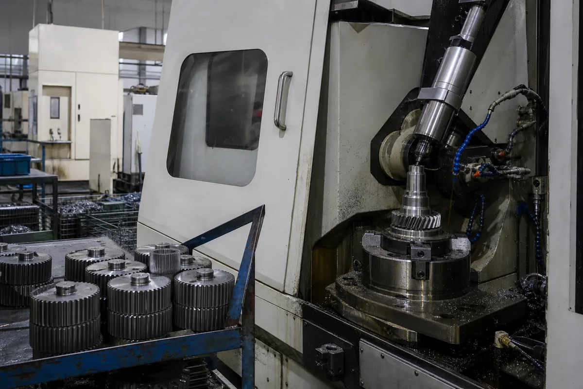
CNC Gear Cutting Capability for Copper
- Multiple gear types
- Profile accuracy class
- Custom modules
- Hardened-blank ready
Copper material properties, finishing options and grade notes are on our CNC Gear Hobbing Copper page.
How CNC Gear Cutting Copper Works
Tooth profiles are generated in the Copper blank by a synchronised cutter, then refined to the required accuracy class. Module, pressure angle and helix are programmed from your gear data.
Programming is driven directly by your 3D model or print. Work-holding, tool selection and the cutting strategy are planned around the critical features and the material before the first chip is cut. First-off inspection confirms the process is centred before production continues.
Achievable Tolerances for CNC Gear Cutting Copper
| Feature | Standard | Precision |
|---|---|---|
| Accuracy class | DIN 8 / AGMA 10 | DIN 6 / AGMA 12 |
| Profile deviation | 0.020 mm | 0.008 mm |
| Lead deviation | 0.020 mm | 0.008 mm |
| Pitch deviation (cumulative) | 0.040 mm | 0.015 mm |
| Runout | 0.030 mm | 0.010 mm |
| Tooth surface finish | Ra 1.6 µm | Ra 0.4 µm (ground) |
| Module range | m0.5–m8 | m1–m6 |
Standard is what a normal quotation assumes. Precision is available on nominated features and is priced separately, because it needs extra setups, in-process gauging and CMM verification. Call out only the features that need it — blanket-tightening a drawing is the single most common reason a quote comes back expensive.
Design Tips for CNC Gear Cutting Copper
We are happy to suggest design tweaks that improve manufacturability. Providing complete gear data (module, pressure angle, profile shift, quality class) lets us produce Copper gears right the first time. If you send your model early, we will return practical DFM feedback before you commit to production.
CNC Gear Cutting Tolerances & Surface Finish
Gear features are produced to a specified DIN/AGMA accuracy class, with profile and lead controlled for quiet, durable running under load.
Exact achievable figures depend on the alloy, the feature size and the part geometry. Tell us which dimensions are critical and we will advise feasibility up front.
Applications of CNC Gear Cutting Copper
Customers order CNC Gear Cutting Copper components for everything from instrumentation to structural and functional assemblies. Whether you need a single prototype or recurring production volume, the same process discipline applies.
Typical Copper Parts for CNC Gear Cutting
Illustrative examples of CNC Gear Cutting Copper parts and the callouts that usually drive the process plan. They show the kind of work that fits this process; they are not specific customer orders.
Worm and wheel set
- Material
- Copper
- Size
- m3, single start
- Key callouts
- Backlash 0.05–0.10 mm as a matched pair
- Batch
- 120 sets
Supplied as matched sets and marked, because mixing pairs loses the backlash spec.
Internal ring gear
- Material
- Copper
- Size
- m2.5, z72, ID 190 mm
- Key callouts
- DIN 8, pitch deviation 0.03 mm
- Batch
- 150 pcs
Shaped rather than hobbed — an internal gear leaves no room for a hob to run out.
Bevel gear pair
- Material
- Copper
- Size
- m2, z20/z40, 90° axes
- Key callouts
- DIN 8, mounting distance ±0.03 mm
- Batch
- 200 sets
Contact pattern checked on a rolling tester before release.
No drawing yet? Build one in the browser.
Set the metal, dimensions and features, watch the 3D model update as you type, then switch to the 2D sheet to add dimensions and tolerances. Download it or send it straight to us with your RFQ.
What We Need to Quote CNC Gear Cutting Copper
- GeometrySTEP or IGES for the 3D model, plus a PDF drawing if you have tolerance callouts. A dimensioned sketch is enough to start.
- MaterialThe exact Copper grade and condition — temper, heat-treat state or hardness. If you are not sure, tell us the function and we will suggest one.
- QuantityPrototype count and the expected annual volume. Both change how the part is made and therefore what it costs.
- TolerancesWhich features are critical. Everything else runs to our standard tolerance, which is what keeps the price sensible.
- FinishSurface treatment, cosmetic requirements, and any faces that must be masked.
- DocumentsWhether you need a material certificate, dimensional report, FAIR or PPAP with the shipment.
Missing something from the list is not a problem — send what you have. We will come back with the specific questions rather than a generic form.
Other Metals for CNC Gear Cutting
Other Processes for Copper
Send the drawing, the Copper grade and the quantity. You get pricing, lead time and any DFM notes back — usually within one business day.
Request a QuoteFrequently Asked Questions
What gear accuracy class can you achieve on Copper?
Gear accuracy is specified to DIN/AGMA classes appropriate to the application. Profile and lead are controlled so Copper gears run accurately and quietly under load.
What is CNC Gear Cutting Copper and how is it done?
CNC Gear Cutting Copper refers to cNC gear cutting forms precise tooth profiles for spur, helical, bevel and worm gears. Applied to Copper — excellent electrical and thermal conductivity — VT machining produces each part to your CAD drawing, selecting parameters from your tolerance, finish and quantity requirements.
Why is Copper a good choice for CNC Gear Cutting?
Copper is excellent electrical and thermal conductivity, which makes it well suited to CNC Gear Cutting. We tune the process to the alloy so the finished Copper gear cutting part meets your dimensional and functional requirements.
How clean are the edges produced by CNC Gear Cutting on Copper?
Machined Copper edges are clean and to specification; edge-break or deburring is added when your drawing calls for it.
What is the typical lead time and minimum order for CNC Gear Cutting Copper?
CNC Gear Cutting prototypes for Copper can be produced quickly and scaled to series production. Send your drawing and quantity and we will advise lead time and any minimum order.